dinsdag 14 april 2015
Knock / clap sensor
I made a knock / clap (loud high frequency sound) sensor to control various things in my room. Three equally spaced knocks press the spacebar om my keyboard, short - long interval turns the lights on, and long - short turns the lights off. I'll post some more information later!
zondag 12 april 2015
New stair lighting
I shone some new light onto one of my bother's old projects at my parents' house, stair lighting. I used the same stuff as in my old home, but with led strips instead of single leds.
zondag 4 januari 2015
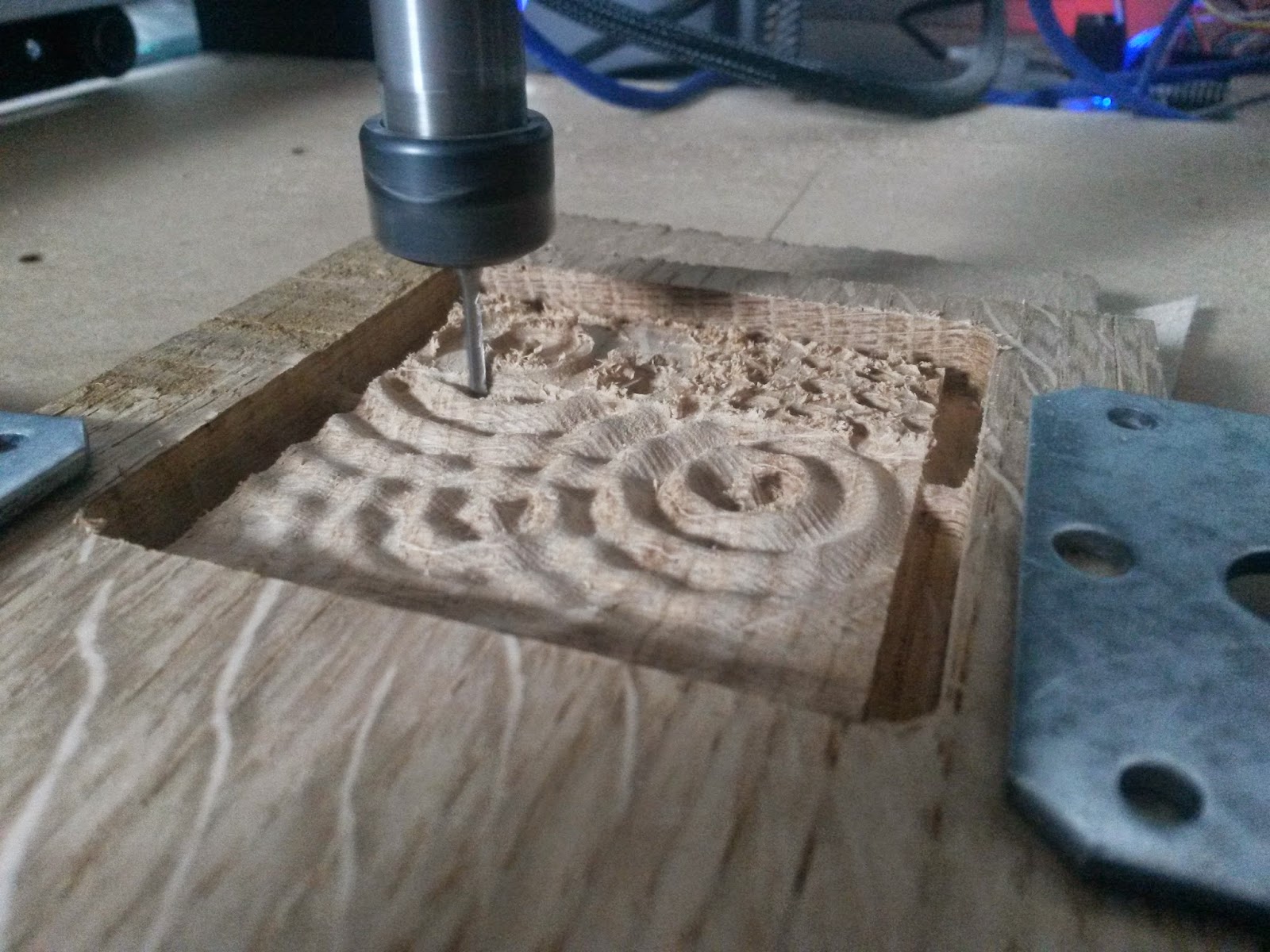
New CNC
My shapeoko is getting kind of small, and I'd like to be able to mill aluminium, so I'm working on a new CNC mill.
The work area will be 600x500mm instead of the shapeoko's 300x300, and I switched from the relatively stretchy timing belts to anti-backlash ballscrews. It does feature the same NEMA23 stepper motors, but these were rather overkill for the shapeoko.
I finished the design a long time ago, and I already have most parts, but I only just got around to finishing the list of required bolts and such.

I am going to have to find myself a bigger desk though.
zaterdag 3 januari 2015


zondag 7 september 2014


Milling PCbs
A couple of students from my school asked me to help them make phone chargers that worked from the dynamo of a bicycle.


(There's still a regulator missing in the last picture, this hadn't been soldered on yet)
vrijdag 27 juni 2014


dinsdag 24 juni 2014
Motorized bicycle
I put the motor from my longboard on my bike to see if that'd work too. It did! The motor does slip a lot, but it still got me going almost 40km/h.


maandag 16 juni 2014


donderdag 1 mei 2014
Undocumented projects
Some random projects. The last three are crafted by a friend of mine, where I did the programming.
Led rings
For a school project we needed to make up something original to add to an amp we were designing. The thing we choose to design was an led ring to be put around each potentiometer.
The ring will consist of sixteen 3mm leds, controlled by two 74hc595 shift registers. In the final version we will use double gang potentiometers, so we can measure it's position without disturbing the audio signal going through it. Because it has to be really small we will use smd shift registers, and smd resistors. This will probably be a pain to solder, but we'll see how it comes along.


woensdag 1 januari 2014
Controlling lights with a gamecube controller.
I've been searching for a way to connect all my projects / lights together, and control them all from one single microcontroller. I've looked at some different radio frequency transceivers, and I have some on the way from china.
The main microcontroller however will need some kind of interface, but I couldn't really figure out what I would like to have for this. One option will be a box with some sliders, buttons, and a nice display, but in the meantime I wanted to try to use an old gamecube controller to control the lights!
Luckily someone wrote a very detailed article about the communication protocol of the controllers, which someone else used to write an arduino program that converts gamecube controller signals to N64 signals. With the arduino program as starting point I could easily read the 12 buttons and 6 potentiometers (2 joysticks and the L and R buttons) from the controller, and control an rgb led with it.
When I receive the rf transceivers I'll see whether it works nicely to control multiple lights with the controller, or that a box with some buttons and a display would be better. If the previous is the case, I'll buy myself a wireless gamecube controller as a remote control for all my projects!
maandag 30 december 2013
vrijdag 27 december 2013
Ordered PCBs
Normally, one of my friends etches the PCBs I design, but there are limits on how small you can make traces on those (and i'm pretty sure he got sick of drilling hundreds of holes every time). So about a month ago I re-designed some of the PCBs to have them made in China, and they finally arrived today!


At the edge of the 10x10cm PCB I had some space left, which I used to make some "led strip connector PCBs", just a small strip where you can solder pieces of led strip on to connect them together. This makes a nice 2.3W RGB LED.
After soldering one board of each kind I strapped them all together; they do their job like chinese factory workers!


I chose the "10pcs 10x10cm" option at iteadstudio, and I really wanted to take full advantage of the 100 square centimeters per board, so I tried to make everything as small as possible, while still using through hole components. The first thing I really wanted to have were some boards for the atmega328 microcontrollers. The one I designed to be etches by my friend were okay, but had were some flaws / things that could be improved:
The crystal didn't really fit, the voltage regulator heatsink blocked the reset button, I never actually used the reset button, it didn't have enough 5v en 0v pins available, it didn't have leds for the Tx and Rx pins, and it used some jumpers, since it was single sided.


It took a lot of time to get the new design small while still having all the extra's on it, but I managed to squeeze it all down to the point where I didn't have a single bit of unused space on the pcb.
To get it this small, I dumped the reset button all together, replaced the 5mm LEDs for small rectangular LEDs, put as much as possible underneath the chip itself, and used a 3mm "Polar" LED for the Rx/Tx. This it an LED with two oppositely connected diodes in it, and I wired it so when Tx is high, and Rx is low, it lights red, and when Tx is low and Rx is high, it lights green. Two leds for the price of one!


Another chip I use a lot is the 74hc595 shift register, and while the original etchable design I made for them was fine, I liked to have a professionally made version aswell. (I did add some capacitors and screw holes in the new design, but didn't change anything else.)
Apart from the shift registers there are some transistor arrays on the PCB. I use these when driving led strips, like in the "light boxes" and the modded IKEA light, but you can also solder resistors in place of the transistor arrays for driving simple LEDs. Another nice feature of these prints is that by placing the headers, you can choose between grouping the outputs as 8 | 8 | 8 or 9 | 6 | 9. The lather is usefull when using RGB LEDs, because then you can simply use eight 3-pin connectors.


At the edge of the 10x10cm PCB I had some space left, which I used to make some "led strip connector PCBs", just a small strip where you can solder pieces of led strip on to connect them together. This makes a nice 2.3W RGB LED.
After soldering one board of each kind I strapped them all together; they do their job like chinese factory workers!


The metal plate is from another IKEA light I'm modding, but it's still a work in progress...

donderdag 19 december 2013
3D Models
While I was working in a laminate flooring store, I made 3d-models to help them plan the expansion of one of their stores.


woensdag 18 december 2013
Amp
I finished my amplifier! I'm pretty sure this is the only recent thing I've built that doesn't have any leds.
maandag 16 december 2013
maandag 9 december 2013
Thermometer
The winter is upon us again, so I made a thermometer, with, you might have guessed it, leds! Since I only need 4 pins for this project, (3 leds pins and 1 sensor pin), I used a small Attiny13 microcontroller. It was a bit tricky fitting all the code in there though, since there is only 1kbyte memory on those things, but I managed to get it working.
When it's 20C, the led is green. This slowly changes over to red at 25C, and blue at 15C
When it's 20C, the led is green. This slowly changes over to red at 25C, and blue at 15C
dinsdag 3 december 2013


donderdag 28 november 2013
Led Cubes!
As someone loving leds, I obviously couldn't nót think about making led cubes. A friend of mine built a 4x4x4 cube a while ago, which I helped programming. (We have this deal that if he needs something programmed, I will do it for him as long as he keeps supplying me with pizzas.) After that, since I already had the code, I built a small one too. (pic 1)
I wanted more than just the small single-colored cube, so I started building an RGB cube. (pic 2). Soldering the thing was terrible though. Each led has 4 pins, only spaced 0.6mm (0.02in) apart, so it was really hard not to accidentally solder some together. It did finish soldering it, but I haven't made the PCB's for it yet.
My friend took the other route, and started building an 8x8x8 cube. (see video). It took him ages to complete, (which makes sense, since there are 1024 leads that need to be soldered), but it was more than worth it. Luckily the same type of hardware could be used, but the old code I used for the small cubes wasn't fast enough for the big one, so I had to rewrite the entire code from scratch. This took quite a while, (and a lot of pizzas), but I'm very pleased with the way the code turned out. I do still have to program some extra modes.


zondag 24 november 2013
Amplifier
My old amplifier broke down a long time ago, and the one I've been borrowing since died on me too. So I built one!
It uses two power op amps, which I have a course dedicated to at school. So making this wasn't that difficult. The box is made from old laminate flooring, and I used an old processor heat sink to cool everything. Instead of making a PCB however, I soldered all the components directly to the op amps. It works, but turned into a big mess, so I don't think I will do it like this again. The only things I need to really finish it are some RCA-connectors, and a nice big volume knob. Although it doesn't really look the part, it sounds way better than expected.


It uses two power op amps, which I have a course dedicated to at school. So making this wasn't that difficult. The box is made from old laminate flooring, and I used an old processor heat sink to cool everything. Instead of making a PCB however, I soldered all the components directly to the op amps. It works, but turned into a big mess, so I don't think I will do it like this again. The only things I need to really finish it are some RCA-connectors, and a nice big volume knob. Although it doesn't really look the part, it sounds way better than expected.


Abonneren op:
Posts (Atom)