zondag 17 december 2017
New website!
Hey everyone. I finally got around making a (slightly more) decent site! I'll be posting my projects on http://redako.nl/ from now on. :)
maandag 14 november 2016
Cross drop plugs
I milled some hardwood plugs for an old friend! Next up Roger wil do the flares, a lot of sanding and a lot of polishing.


zondag 13 november 2016
vrijdag 15 april 2016
Home summary
We had to say goodbye to our home in Leiden, but made a small tribute film with some of the things we did together.
zondag 22 november 2015
Fancy LEDs.
I'm getting tired of some of the cheap chinese low light quality leds I have hanging around my house, and I've got a bunch of fancy 2700K 90+CRI leds laying around somewhere, but I did not yet have a PCB to put them on.
I wanted to stay below the 50x50mm limit for the cheapest option at the boardhouse, and managed to get 30 of the 5630 LEDs on it. At about 30 lumen per LED this should compare to a 75 watt incadicent bulb, which is pretty neat for the 9W the LEDs will consume. Each LED has it's own small top and bottom copper plane for thermal reasons. Pictures:


Edit:
I got my PCBs and stencil! I just have to wait for the resistors, and then it's time to bake.
I got my PCBs and stencil! I just have to wait for the resistors, and then it's time to bake.


Another edit:
All done!


donderdag 29 oktober 2015
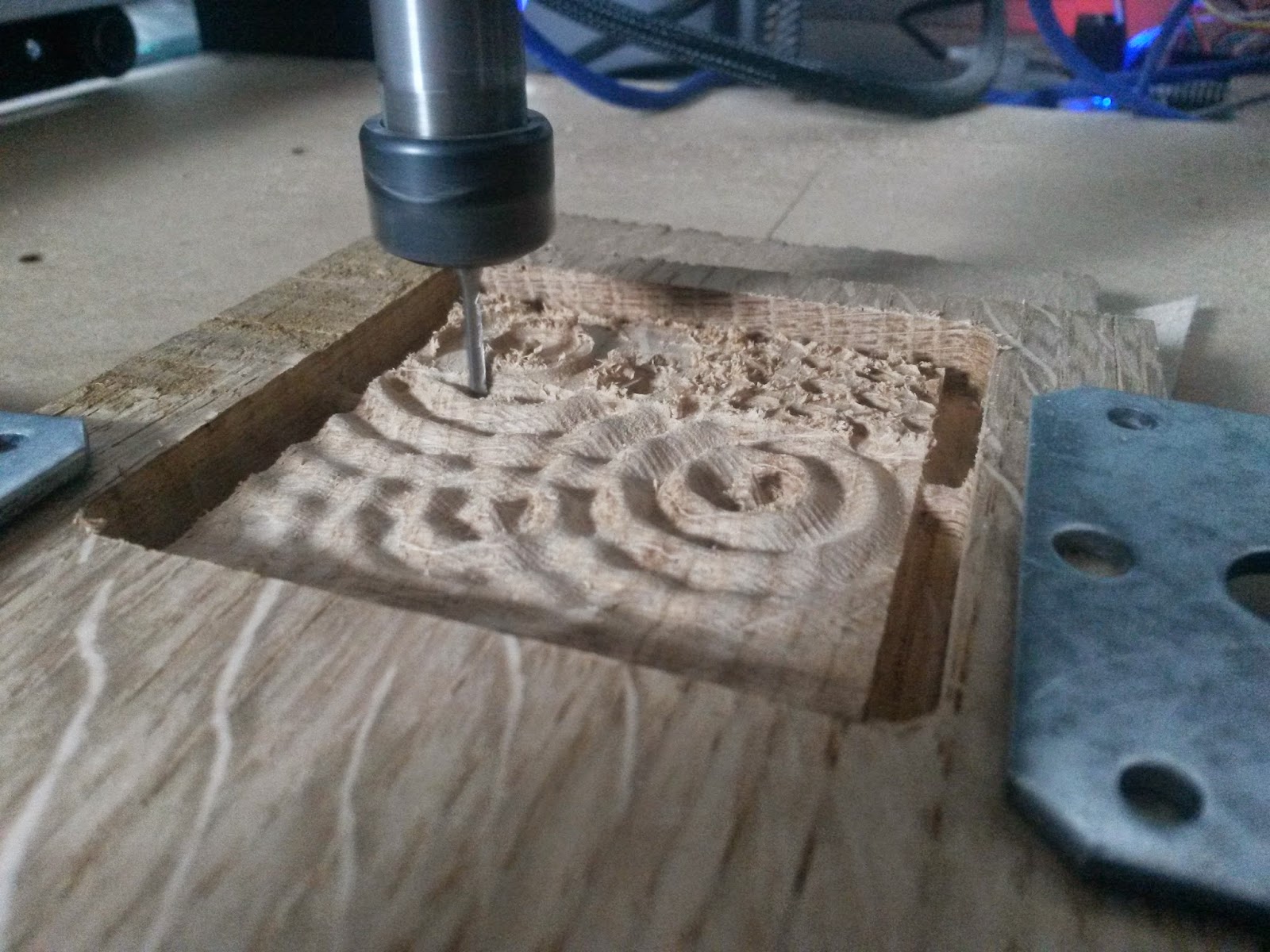
Valentine's day pendant
Last valentine's day I made a heart shaped pendant out of padauk with the help of my cnc, a few square meters of sandpaper, and some danish oil.


dinsdag 21 juli 2015
Welcome to the Village
I joined D-Exto, the organisation that asked us to make the LED roof, to the Welcome to the Village festival as volunteer! I had a great time and met a lot of interesting people. I spent most my free time walking around making pictures, Here are some of the pictures.
- More to be typed here
- More to be typed here
dinsdag 30 juni 2015
Making everything wireless; PCBs.
For a long time I've had the plan to make all my projects wirelessly controllable, but I never really found a cheap, reliable module. I experimented with simple 433Mhz RF modules, zigbee modules, and wifi modules before I found the 2.4GHz NRF module I ended up using.
With the simple RF modules the arduino had to do the encoding and such itself, this didn't work really well for me and meant less processing power for other stuff. The zigbee modules were all quite expensive, but did work well. Wifi became pretty interesting when the ESP modules started coming up, but having 20 wifi devices on my router might become somewhat impractical, and I didn't feel like I needed all the TCP handshakes and such.
The 2.4Ghz (NRF24l01+) modules were really cheap, and worked straight out of the box with a pretty clear library. The downside to these were that the library I picked used the hardware SPI pins, which I also used in the shiftPWM library to control a bunch of LEDs in the first project I wanted to make wireless. At the time I didn't really get all the C++ stuff in the library, so I didn't think if touching the library itself. It was a few months later when I had an actual C++ course at my study and tried to implement software SPI instead. This did take quite some time to get right, apparently the atmega locks the use of the hardware SPI pins once you have initialized the SPI mode. Once I got this sorted out and the software SPI worked the modules became pretty flexible to use. I made the room lighting I had at the time wireless with these modules, but it always turned into a big wirey mess. To solve this, and make it really easy to add new devices, I started designing PCBs for the module.


On the first version I had an Arduino pro mini, an NRF module, and, because I had space left, an ESP Wifi module aswell. For the 5 and 3.3v regulators I used through hole ones, because they use less board size than standard SOT-232 regulators. On the bottom are 6 smd 4A N-channel mosfets hooked up to the atmega's PWM pins. On one of those there is place for a TO-220 mosfet aswell, might I need more than the 4A the small ones can deliver. All the headers at the top are used to break out the atmega's analog and SPI pins.
The downside to this version was that it was really high. The TO-220 regulators and mosfet made it hard to fit in a small box, and when programming it the USB-Serial converter had to go in vertically.


To make everything a lot smaller I went with an Arduino Nano on the next version. This saves me a 5V regulator, since there is one on the Nano itself. I also redid the layout for a bit, and added an optional ldr and temperature / humidity sensor. I also replaced the last two TO-220 packages with smd versions, and removed the electrolytic capacitor that I never really used. One addition was the possibility to place diodes at the mosfets, for when switching inductive loads.
Most adapters I used had a DC jack though, so one thing I almost always had to do when hooking light up to the boards was screw a female DC jack to the screw terminal. This was rather anoying, so the next version had to have a DC jack itself. The two modules sticking out at the end were also quite anoying. I also switched from Ultiboard to Circuit maker here, so the 3D previews are a bit more fancy.


On the order with the previous PCBs I had a bit of space left. I order my PCBs on dirtyPCBs.com, where you can just fill a 10x10cm piece with whatever you want, and get 10 of those for $25. If you use less of the 10x10 shape it won't save you any money, so I had to think of something to fill the bit I had left. When making the smartphone controlled looping louie I wanted to put the board into the base of the game itself, but that didn't fit. For this I made a really small pcb, with only the NRF module and it's 10uF capacitor. This way I can upgrade every Arduino Nano with wireless capabilities!
With the simple RF modules the arduino had to do the encoding and such itself, this didn't work really well for me and meant less processing power for other stuff. The zigbee modules were all quite expensive, but did work well. Wifi became pretty interesting when the ESP modules started coming up, but having 20 wifi devices on my router might become somewhat impractical, and I didn't feel like I needed all the TCP handshakes and such.
The 2.4Ghz (NRF24l01+) modules were really cheap, and worked straight out of the box with a pretty clear library. The downside to these were that the library I picked used the hardware SPI pins, which I also used in the shiftPWM library to control a bunch of LEDs in the first project I wanted to make wireless. At the time I didn't really get all the C++ stuff in the library, so I didn't think if touching the library itself. It was a few months later when I had an actual C++ course at my study and tried to implement software SPI instead. This did take quite some time to get right, apparently the atmega locks the use of the hardware SPI pins once you have initialized the SPI mode. Once I got this sorted out and the software SPI worked the modules became pretty flexible to use. I made the room lighting I had at the time wireless with these modules, but it always turned into a big wirey mess. To solve this, and make it really easy to add new devices, I started designing PCBs for the module.


On the first version I had an Arduino pro mini, an NRF module, and, because I had space left, an ESP Wifi module aswell. For the 5 and 3.3v regulators I used through hole ones, because they use less board size than standard SOT-232 regulators. On the bottom are 6 smd 4A N-channel mosfets hooked up to the atmega's PWM pins. On one of those there is place for a TO-220 mosfet aswell, might I need more than the 4A the small ones can deliver. All the headers at the top are used to break out the atmega's analog and SPI pins.
The downside to this version was that it was really high. The TO-220 regulators and mosfet made it hard to fit in a small box, and when programming it the USB-Serial converter had to go in vertically.


To make everything a lot smaller I went with an Arduino Nano on the next version. This saves me a 5V regulator, since there is one on the Nano itself. I also redid the layout for a bit, and added an optional ldr and temperature / humidity sensor. I also replaced the last two TO-220 packages with smd versions, and removed the electrolytic capacitor that I never really used. One addition was the possibility to place diodes at the mosfets, for when switching inductive loads.
Most adapters I used had a DC jack though, so one thing I almost always had to do when hooking light up to the boards was screw a female DC jack to the screw terminal. This was rather anoying, so the next version had to have a DC jack itself. The two modules sticking out at the end were also quite anoying. I also switched from Ultiboard to Circuit maker here, so the 3D previews are a bit more fancy.


Apart from adding the DC jack I removed a lot as well. The arduino library uses one of the atmega's timers to count all milliseconds and microseconds since it started. This is pretty usefull because I don't have to use any timers to run a bit of software every so much seconds. The downside to this is that you can't really change this timer's frequency, and thus can't increase the PWM frequency of the two connected PWM pins. For lighting the standard 1000Hz frequency is, in my opinion, a bit too low. So on the new board I removed the two mosfets from these pins.
The ESP modules on the two previous boards were also never used, so those could go too. The large humidity sensor didn't get placed either, so I removed that aswell. If I would feel like using one I could easily grab one of the older boards. I did place a small digital thermometer in it's place, and kept the LDR. Another change is the use of a smaller version of the NRF module. It works exactly the same, but is smaller. No reason to keep the big one! I also put the capacitor back, because some cheap chinese power supplies tend to make a lot of noise without it, and again changed the layout. I now ended up with a pcb that I can't think of improving yet. (:


On the order with the previous PCBs I had a bit of space left. I order my PCBs on dirtyPCBs.com, where you can just fill a 10x10cm piece with whatever you want, and get 10 of those for $25. If you use less of the 10x10 shape it won't save you any money, so I had to think of something to fill the bit I had left. When making the smartphone controlled looping louie I wanted to put the board into the base of the game itself, but that didn't fit. For this I made a really small pcb, with only the NRF module and it's 10uF capacitor. This way I can upgrade every Arduino Nano with wireless capabilities!
donderdag 4 juni 2015
LED Roof
For an organisation in Delft I was asked to build/repair an LED roof. What they had didn't work because of very long signal wires and because the old builders underestimated the voltage drop caused by the large currents required to drive 8640 individual leds at 5 volts, (about 170 amps, theoretically). With a team from my school we took the old roofs apart and rebuilt it with heavy copper strips, 25mm² cables, and microcontrollers embedded in the roof itself.
Now that the roof functions well, the real work only begins. So far the only modes implemented during the testing are a screensaver, and one "music" mode where the roof wirelessly receives information from a separate transmitter. There is a lot of work put into the roof, so there's also a lot of programming to do to make that count. The video's are still from the all the tests, but the roof will be on it's first festival tomorrow. I hope to make some better videos there.
Now that the roof functions well, the real work only begins. So far the only modes implemented during the testing are a screensaver, and one "music" mode where the roof wirelessly receives information from a separate transmitter. There is a lot of work put into the roof, so there's also a lot of programming to do to make that count. The video's are still from the all the tests, but the roof will be on it's first festival tomorrow. I hope to make some better videos there.
Making everything wireless
I moved to a new apartment and decided to (finally) make everything in my house wirelessly controllable. So far I've designed, ordered, and tested four versions of a control-everything-in-my-house-wirelessly-PCB and started writing a library to manage all the devices easily without creating a giant mess. I'll tell more about the PCBs in another post, but I'd like to have a post with some results first.
The initial purpose for the first batch of PCBs was to control all lights in the house. For the first test I took the knock sensor from my latest post, added a potentiometer, and one of the boards, and shoved it in an ikea drawer. I already had a glass sphere from an older project, and hooked a 20W Philips lumiled (LHC1-2790-1205) in it to another board.
The test worked so well I immediately put the boards in every light I had laying around. I also upgraded the ikea drawer with some touch sensors, because, well, why not.
Because of more unknown reasons it felt like a good idea to make an 'audio/video' transmitter. It takes the average color of my screen with a processing sketch, and sends this together with the intensity of the music to the lights. It's quite disco.
Last but not least it was insanely simple to hook up a motor to the board too. This got us from the idea to make the game looping louie smartphone controlled, to an actual smartphone controlled looping louie in about 3 minutes. The app is made by a classmate and communicates to the boards through a wifi module. It controls the lights and everything else as well.
dinsdag 14 april 2015
Knock / clap sensor
I made a knock / clap (loud high frequency sound) sensor to control various things in my room. Three equally spaced knocks press the spacebar om my keyboard, short - long interval turns the lights on, and long - short turns the lights off. I'll post some more information later!
zondag 12 april 2015
New stair lighting
I shone some new light onto one of my bother's old projects at my parents' house, stair lighting. I used the same stuff as in my old home, but with led strips instead of single leds.
zondag 4 januari 2015
New CNC
My shapeoko is getting kind of small, and I'd like to be able to mill aluminium, so I'm working on a new CNC mill.
The work area will be 600x500mm instead of the shapeoko's 300x300, and I switched from the relatively stretchy timing belts to anti-backlash ballscrews. It does feature the same NEMA23 stepper motors, but these were rather overkill for the shapeoko.
I finished the design a long time ago, and I already have most parts, but I only just got around to finishing the list of required bolts and such.

I am going to have to find myself a bigger desk though.
zaterdag 3 januari 2015


zondag 7 september 2014


Milling PCbs
A couple of students from my school asked me to help them make phone chargers that worked from the dynamo of a bicycle.


(There's still a regulator missing in the last picture, this hadn't been soldered on yet)
vrijdag 27 juni 2014


dinsdag 24 juni 2014
Motorized bicycle
I put the motor from my longboard on my bike to see if that'd work too. It did! The motor does slip a lot, but it still got me going almost 40km/h.


maandag 16 juni 2014


Abonneren op:
Posts (Atom)